

1. Technical Foundations & Physics of Power Measurement Transformers
In modern electrical engineering, Power Measurement Transformers (often classified under instrument transformers, including precision current sense transformers and potential/voltage transformers) serve as the critical analog front-end interface between high-voltage/high-current distribution networks and sensitive digital metering, relay protection, and IoT power analytics hardware. Unlike standard step-down power transformers designed strictly for bulk energy transfer, measurement transformers prioritize linear ratio accuracy, minimal phase angle displacement ($\delta$), thermal resistance stability, and total harmonic distortion (THD) suppression across wide dynamic current operating ranges.
As electrical grids evolve from centralized fossil-fuel generation to decentralized, bidirectional microgrids incorporating solar inverters, battery energy storage systems (BESS), and high-frequency electric vehicle fast chargers (EVSE), the requirements for power measurement precision have reached unprecedented stringency. Engineers and procurement directors must evaluate magnetic components not merely by nominal current ratings, but by core saturation flux density ($B_{max}$), excitation current ($I_e$), excitation admittance, and temperature coefficients over long service lifetimes (often exceeding 25–30 years).
Information Gain Concept: Understanding Phase Error ($\delta$) vs. Ratio Correction Factor (RCF)
In revenue-grade metering applications (such as ANSI C57.13 Class 0.2S or IEC 61869-2 Class 0.2S), total energy calculation error is dictated by two distinct parameters:
- Ratio Correction Factor (RCF): The multiplier used to correct the nominal secondary voltage or current output to match actual primary values. Core permeability variations at low current thresholds directly impact RCF.
- Phase Angle Displacement ($\delta$): The phase shift between primary and secondary vector waveforms (measured in minutes or milliradians). In low power factor environments (e.g., $PF < 0.5$), even a 10-arcminute phase shift introduces exponential revenue billing errors.
Triad Magnetics engineers custom magnetic topologies that systematically minimize phase shift by employing advanced high-permeability toroidal core structures—utilizing ultra-thin silicon steel laminations, nickel-iron alloys (Mu-metal), and state-of-the-art nanocrystalline amorphous ribbons. By optimizing coil symmetry and minimizing leakage inductance ($L_l$), our power measurement transformers ensure sub-0.1% amplitude stability across operating frequencies from 45 Hz up to 500 kHz in switch-mode topology sensing.
2. Global Standard Compliance & Precision Accuracy Classes
Navigating global procurement requires rigorous alignment with international electrical standards. Power measurement transformers built by Triad Magnetics comply with strict safety, isolation, and metering frameworks including UL, CSA, IEC, and IEEE standards.
| Accuracy Class | Standard Framework | Ratio Error Limit (@ Rated Current) | Phase Displacement Limit ($\delta$) | Primary Application Area |
|---|---|---|---|---|
| Class 0.1 | IEC 61869-2 / IEEE C57.13 | ±0.1% | ±5 Minutes (1.45 mrad) | Laboratory Reference Calibration, Precision Grid Meters |
| Class 0.2S | IEC 61869-2 (Extended Low Current) | ±0.2% (down to 1% nominal current) | ±10 Minutes (2.90 mrad) | Revenue Metering, Substation Utility Billing, Microgrids |
| Class 0.5 | ANSI C57.13 / IEC 60044-1 | ±0.5% | ±30 Minutes (8.70 mrad) | Industrial Automation, Motor Control Centers (MCC), Switchgear |
| Class 1.0 / 3.0 | Industrial General Purpose | ±1.0% to ±3.0% | ±60 to 120 Minutes | Fault Monitoring, Overcurrent Protection Relays, Solar Inverters |
To maintain Class 0.2S performance across extreme thermal gradients ($-40^\circ\text{C}$ to $+85^\circ\text{C}$), our engineering team utilizes computer-controlled automated toroidal winding machines and custom potted encapsulation using UL 94V-0 compliant flame-retardant epoxy resins. This eliminates mechanical magnetostriction noise and prevents environmental ingress in outdoor smart grid installations.
3. Recommended Triad Product Solutions for Measurement & Sensing
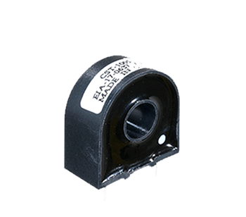
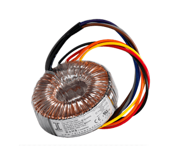
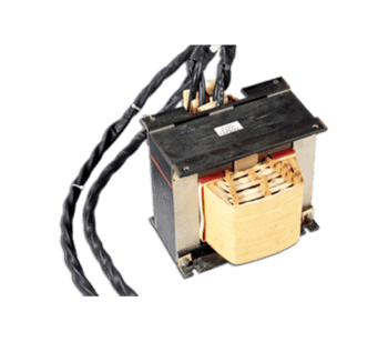
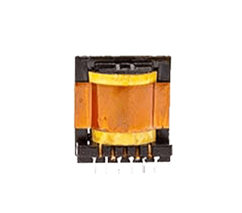
Explore our core catalog and custom OEM magnetics designed for power measurement, current monitoring, and line voltage sensing. Each component is engineered, manufactured, and tested to rigorous quality standards in our ISO 9001:2015 certified facilities.
4. Why Global OEMs Partner with Triad Magnetics (E-E-A-T & Quality Focus)
For more than 75 years, Triad Magnetics has maintained a position as an industry pioneer in custom magnetic component manufacturing. Founded in 1946, our experience spans pioneering audio transformers for Hollywood sound studios to high-frequency switch-mode power supplies and revenue-grade current measurement devices for global energy infrastructure.
Triad Magnetics Engineering & Quality Excellence At A Glance
- ISO 9001:2015 Certification: Fully documented quality control systems across design, prototyping, production, and incoming raw material inspection.
- Dual-Shore Manufacturing Model: Strategic production capabilities located in California, USA and our state-of-the-art facility in the Philippines, providing flexible volume scaling, supply chain resiliency, and competitive total cost of ownership.
- 100% End-of-Line Verification: Every measurement transformer undergoes automated testing for turns-ratio accuracy, excitation current, DC resistance (DCR), phase displacement, and high-voltage dielectric insulation withstand testing (Hi-Pot).
- Regulatory Agency Approvals: Extensive portfolio of standard designs compliant with UL (Class 130(B), 155(F), 180(H) insulation systems), CSA, CE, TUV, and RoHS/REACH environmental standards.
Our engineering team in Perris, California works directly with OEM design teams from prototype design through production validation. By conducting finite element magnetic field modeling (FEM) and thermal simulation early in the design cycle, we eliminate core saturation risks and phase drift before tooling production begins.
5. Emerging Industry Trends Shaping Future Magnetics Procurement (2026–2030)
Global procurement leaders must anticipate technological shifts when sourcing power measurement transformers. Over the next decade, four key macro-trends are reshaping component design and vendor evaluation criteria:
Trend 1: Microgrids, BESS, and Bidirectional Energy Flow
Traditional utility transformers were optimized for unidirectional AC power flow from central power plants to consumers. Modern microgrids feature intermittent distributed energy resources (DERs) like rooftop PV arrays, battery storage, and V2G (Vehicle-to-Grid) electric vehicle chargers. Measurement transformers must maintain high accuracy during rapid power reversals and extreme current ramp rates without remnant magnetization of the core core structure.
Trend 2: Wide-Bandgap Power Electronics (SiC and GaN) Integration
Silicon Carbide (SiC) and Gallium Nitride (GaN) switching devices enable power converters to operate at switching frequencies exceeding 100 kHz to 1 MHz with high $dV/dt$ voltage gradients. Standard laminated steel instrument transformers experience catastrophic eddy current losses at high frequencies. Global buyers are increasingly specifying nanocrystalline and low-loss manganese-zinc (MnZn) ferrite cores with high high-frequency common-mode rejection to accurately sense high-order power quality harmonics up to the 100th harmonic order.
Trend 3: AI-Driven Predictive Maintenance & Smart Substation IoT
Smart substations are transitioning from analog monitoring to optical and digital IEC 61850 process bus networks. Power measurement transformers now often integrate embedded micro-sensors, Rogowski coil secondary windings, or dual-core topologies (combining a high-precision metering core with a high-saturation protection core) to supply real-time power analytics directly to AI predictive maintenance edge gateways.
Trend 4: Sustainable Materials & Circular Supply Chain Standards
Environmental, Social, and Governance (ESG) mandates are driving global procurement teams to evaluate vendor carbon footprints, Conflict Minerals compliance, and energy-efficient manufacturing processes. Triad Magnetics prioritizes 100% lead-free assembly, halogen-free insulating materials, and recycled copper sourcing across our global manufacturing footprint.
6. Frequently Asked Questions (FAQ) for OEM Buyers & Engineers
Here are detailed responses to the most critical technical and supply chain queries encountered by electrical design engineers and global sourcing professionals.
Answer: The fundamental difference lies in their optimization goals. A power supply transformer is designed for efficient, bulk energy transfer with high power density and voltage transformation ratio stability under variable power loads. In contrast, a Power Measurement Transformer (or instrument transformer) is optimized strictly for signal measurement fidelity. It operates under near zero-power transfer conditions (into high-impedance meters or low-burden shunts) to deliver extreme amplitude linearity (sub-0.1% error) and minimal phase angle shift ($\delta$) across broad dynamic current and temperature ranges.
Answer: Phase error is directly caused by the excitation current ($I_e$) required to magnetize the transformer core. Core materials with low initial magnetic permeability ($\mu_i$) demand higher excitation current, creating a vector phase lag between primary and secondary signals. Standard silicon steel cores exhibit phase shifts of 30 to 90 arcminutes. High-permeability Nickel alloys (80% Ni / Permalloy) reduce phase error to under 10 arcminutes, while nanocrystalline amorphous core matrices achieve phase errors under 2 to 5 arcminutes across 1% to 120% of rated nominal current.
Answer: The "S" designation signifies "Special" accuracy extended across exceptionally light current loads. A conventional Class 0.2 transformer guarantees 0.2% accuracy only between 100% and 120% of rated nominal current. A Class 0.2S transformer maintains its strict 0.2% ratio error down to 20% of nominal load, and guarantees maximum 0.75% ratio error even at 1% of nominal load. This capability is critical for smart energy billing where loads fluctuate dramatically (such as solar farms during sunrise/sunset or idle EV charging stations).
Answer: Under normal operation, the secondary current produces a counter-magnetic flux that opposes the primary MMF (magnetomotive force), keeping net core flux low. If the secondary circuit is opened while primary current flows, the opposing secondary MMF disappears. The entire primary current becomes excitation current, driving the magnetic core into extreme saturation. This induces dangerous peak voltage spikes (several kilovolts) across the open secondary terminals—posing severe electrical shock hazards to technicians and destroying internal coil insulation. Triad offers self-protecting current transformers with built-in internal voltage clamps or burden resistors to prevent open-circuit catastrophic failure.
Answer: Triad maintains a dedicated fast-track custom engineering department in Perris, California. Our engineering team utilizes advanced magnetic simulation software, rapid 3D bobbin prototyping, and automated sample winding tools. Prototype samples can typically be delivered within 2 to 4 weeks depending on material availability and custom encapsulation requirements. Once approved, production can seamlessly scale between our domestic USA plant and our high-volume offshore manufacturing plant in the Philippines.
Answer: Triad offers magnetic components certified to UL Insulation Systems ranging from Class 130(B) [$130^\circ\text{C}$] up to Class 180(H) [$180^\circ\text{C}$] under UL file insulation system designations. All potting compounds are certified UL 94V-0 flame retardant. For medical instrumentation and high-isolation industrial equipment, we engineer units with reinforced dielectric isolation capable of withstanding Hi-Pot insulation dielectric testing up to 4,000V RMS or 5,600V DC.
Partner with Triad Magnetics for Precision Power Measurement Solutions
Whether you require catalog evaluation samples, custom Class 0.2S revenue-grade toroidal CTs, or high-frequency wideband measurement magnetics, our application engineers are standing by to review your schematic and mechanical requirements.