

1. Executive Overview & Semantic Landscape of Power Conversion Magnetics
In modern electronic systems, Power Conversion Magnetics form the indispensable physical foundation of energy management. Whether stepping down high-voltage grid AC to low-voltage DC for sensitive microprocessors, stepping up battery power for electric vehicle traction drives, or filtering electromagnetic interference (EMI) in medical diagnostic equipment, magnetic components—including transformers, power inductors, and filtering chokes—determine overall efficiency, volumetric power density, and operational reliability.
As switching power supplies evolve from traditional silicon (Si) MOSFETs operating below 100 kHz toward wide-bandgap (WBG) semiconductors such as Gallium Nitride (GaN) and Silicon Carbide (SiC) running at frequencies exceeding 500 kHz to 2+ MHz, the demands placed on power conversion magnetics have fundamentally transformed. Power conversion is no longer merely a matter of copper turns around an iron core; it is a sophisticated discipline balancing high-frequency magnetic core loss, skin and proximity effects, parasitic leakage inductance, interwinding capacitance, thermal dissipation, and international safety compliance.
From a system architecture perspective, power conversion magnetics operate as reactive energy storage and galvanic isolation nodes. Unlike passive power pass-through devices, they experience intense transient flux density shifts ($\Delta B$), high thermal gradients, and steep $dV/dt$ voltage edges. Proper specification requires analyzing both zero-voltage switching (ZVS) resonant states and hard-switched continuous conduction mode (CCM) stress factors.
2. Recommended Product Families for Power Conversion Applications
Global procurement specialists and senior power supply engineers require tailored magnetic components designed for specific circuit topologies. Below are Triad Magnetics’ primary component architectures optimized for modern energy conversion infrastructure.
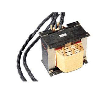
Custom High-Frequency Magnetics
Tailored flyback, push-pull, half-bridge, and full-bridge LLC resonant transformers designed to maximize efficiency in compact enclosure footprints.
View Custom Engineering Capabilities →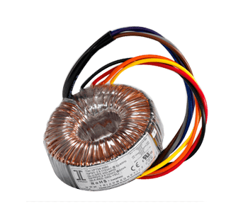
Power & SMPS Transformers
Off-the-shelf and custom switch-mode power transformers featuring low core losses, high isolation voltage (up to 4000VAC), and Class B/F/H thermal ratings.
Explore Power Transformers →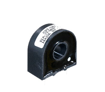
Current Sense Transformers
High-accuracy current sensing transformers for peak current mode control, over-current protection, and digital energy measurement systems up to 50 Amps.
Inspect Current Sense Lineup →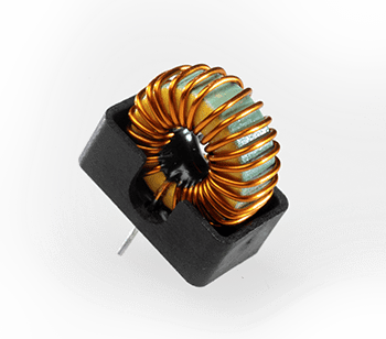
Dual-Function Chokes & Power Inductors
Innovative dual-function chokes combining common-mode and differential-mode attenuation in a single compact core to cut PCB bill-of-materials (BOM) costs.
Browse Inductors & Chokes →3. Technical Performance Matrix: Matching Magnetics to Power Topologies
Selecting the optimal power conversion magnetic component depends heavily on power level, operating frequency, and isolation requirements. The engineering matrix below correlates core parameters to common application topologies.
| Power Converter Topology | Typical Frequency Range | Core Material Selection | Key Magnetic Design Challenge | Triad Recommended Solution |
|---|---|---|---|---|
| Flyback Converter (<150W) | 65 kHz – 300 kHz | MnZn Ferrite (High Saturation) | Managing leakage inductance & primary voltage spikes | Custom Interleaved Windings & Shielded EF/ETD Cores |
| LLC Resonant Converter (100W–2kW) | 100 kHz – 500 kHz | Low-Loss High-Freq Ferrite / Nanocrystalline | Precise control of resonant magnetizing & leakage inductance | Sectioned Bobbin Integrated LLC Transformers |
| PFC Boost Inductor (500W–5kW) | 50 kHz – 200 kHz | Fe-Si-Al (Sendust) / High-Flux Powder | Maintaining inductance under high DC bias current | Toroidal & E-Core Sendust Power Inductors |
| Medical Grade Power Supply | 100 kHz – 400 kHz | MnZn Ferrite + Reinforced Insulation | Compliance with 2MOPP, low leakage current (<10 µA) | IEC 60601-1 Triple Insulated Wire (TIW) Transformers |
| GaN-Driven Ultra-Dense Charger | 500 kHz – 2+ MHz | Ultra-Low Loss Ferrite / Planar Substrates | Extreme AC winding loss (Skin Effect) & high dV/dt EMI | Planar Magnetics with Flat Copper Foil Windings |
4. Deep-Dive Architecture: Wide-Bandgap (GaN & SiC) Integration Challenges
The global shift toward Gallium Nitride (GaN) and Silicon Carbide (SiC) power switches represents the most significant paradigm shift in power conversion over the past two decades. While GaN and SiC devices enable dramatic reduction in semiconductor conduction and switching losses, they impose harsh operating conditions on surrounding magnetic structures.
Minimizing High $dV/dt$ Parasitic Ringing
GaN transistors switch in nanoseconds, producing voltage rise rates ($dV/dt$) exceeding 100 V/ns. When exposed to high $dV/dt$ steps, the parasitic interwinding and intra-winding capacitance of a conventional transformer conducts high displacement currents ($i = C \cdot dV/dt$). This induces severe high-frequency ringing, electromagnetic interference (EMI) spikes, and potential false-triggering of gate driver circuits.
To eliminate these parasitics, Triad Magnetics employs specialized winding layouts including balance-shielding techniques, triple-insulated wire (TIW) separation, and controlled spacing bobbins that reduce primary-to-secondary capacitance down to single-digit picofarads (pF).
Mitigating AC Resistance: Skin & Proximity Effects
At high switching frequencies, current within a copper conductor redistributes toward the outer surface—a phenomenon known as the skin effect. Concurrently, magnetic fields generated by adjacent conductor turns force current into localized channels, compounding losses via the proximity effect. At 500 kHz, the skin depth of copper drops to approximately 0.093 mm.
Using thick solid magnet wire at high frequencies results in catastrophic thermal dissipation. Triad’s high-frequency power conversion magnetics utilize custom Litz wire configurations—composed of hundreds of individually insulated fine copper strands—or multi-layer planar PCB copper tracks to ensure low AC-to-DC resistance ratios ($R_{AC} / R_{DC} \approx 1.1$).
5. Future Procurement & Technology Trends in Power Conversion Magnetics
For global procurement teams, sourcing power conversion magnetics requires balancing unit cost against long-term operational risk, technical evolution, and supply chain elasticity. Key macro trends reshaping the industry through 2030 include:
Trend 1: Demand for Higher Power Density & Modular Planar Topologies
Industrial, datacenter, and automotive OEM applications demand ever-smaller power supply enclosures. Planar magnetics—which replace traditional wire-wound coils with multi-layer printed circuit boards (PCBs) or flat copper stampings integrated into low-profile ferrite cores—are expanding rapidly. Planar architectures offer consistent parasitic parameters, thermal dissipation capability up to 30W/cm³, and automated PCB manufacturing compatibility.
Trend 2: Transition to Sendust and Nanocrystalline Core Materials
While MnZn ferrites remain dominant for high-frequency transformers, power factor correction (PFC) and grid-tied solar inverter inductors are transitioning toward Sendust (Fe-Si-Al) and Nanocrystalline ribbon alloys. Nanocrystalline cores offer exceptionally high saturation flux density ($B_s \approx 1.2\text{ T}$) and high initial permeability over wide temperature ranges (-40°C to +150°C), enabling up to 40% volume reduction in high-current filtering chokes.
Trend 3: Supply Chain Resiliency via Regionalized Dual-Sourcing
Recent global logistics vulnerabilities have highlighted the risk of single-source manufacturing. OEM buyers now require dual-plant manufacturing footprints. Triad Magnetics addresses this risk by offering seamless dual-sourcing: domestic engineering prototyping and short-run production in California, USA, paired with high-volume, cost-optimized production in the Philippines. Both facilities operate under unified ISO 9001:2015 quality frameworks and identical test protocols.
6. Enterprise Advantages & E-E-A-T: Why Global OEMs Partner with Triad Magnetics
Since 1946, Triad Magnetics has pioneered magnetics engineering innovation—from supplying critical components for NASA's Apollo lunar missions to powering today’s medical equipment, industrial automation systems, and renewable energy infrastructure. Our operational authority rests on four pillars of engineering excellence:
- 75+ Years of Electromagnetic Design Expertise: Over seven decades of proprietary engineering data, thermal modeling algorithms, and empirical coil winding mastery.
- Comprehensive Safety Certification Matrix: Deep familiarity with international regulatory standards, including UL 5085 (Class 2 & 3), UL 60950-1, IEC 62368-1, and IEC 60601-1 (Medical 4th Edition). Insulation systems rated up to Class H (180°C).
- Rigorous 100% In-Line Production Testing: Every standard and custom unit undergoes automated testing for turns ratio, primary inductance, leakage inductance, DC resistance, and high-potential dielectric breakdown (HIPOT up to 4500VAC).
- Expedite Custom NPI (New Product Introduction): Rapid custom prototyping turnaround with dedicated application engineering support from initial schematic concept to high-volume manufacturing approval.
7. Frequently Asked Questions (FAQ) for OEM Engineers & Buyers
Below are expert responses to queries frequently posed by power electronics designers and procurement specialists when evaluating power conversion magnetics.