

1. Executive Overview & Market Alignment: The High Frequency Revolution
In modern power electronics, the transition toward higher power densities, reduced physical footprints, and ultra-high efficiency has redefined magnetic component design. As wide-bandgap (WBG) semiconductors—specifically Gallium Nitride (GaN) and Silicon Carbide (SiC)—advance operating switching frequencies from traditional 50 kHz limits up into 500 kHz to 3 MHz+ regimes, standard off-the-shelf magnetics introduce unacceptable parasitic losses, thermal hot-spots, and severe electromagnetic interference (EMI).
Engineers and global procurement managers can no longer rely on legacy magnetic components. Achieving high efficiency requires Custom High Frequency Magnetics tailored specifically to the switching frequency, thermal dissipation geometry, skin depth constraints, and parasitic capacitance thresholds of next-generation power topologies. Whether designing high-density Switch-Mode Power Supplies (SMPS), resonant LLC converters for AI data centers, industrial automation drivers, or IEC 60601-1-compliant medical power systems, custom magnetic design directly governs system reliability and compliance.
Information Gain Insight: Conventional vs. High-Frequency Custom Magnetics
While standard low-frequency magnetics rely on bulky silicon steel laminated cores and heavy copper wire to prevent magnetic saturation, Custom High Frequency Magnetics utilize advanced MnZn/NiZn ferrite geometries, planar PCB winding layouts, and specialized Litz wire. This shift reduces magnetic component volume by up to 65% while maintaining electrical isolation and suppressing high-frequency eddy-current losses.
| Design Criteria | Standard Power Magnetics (50 Hz - 20 kHz) | Custom High Frequency Magnetics (100 kHz - 3 MHz+) |
|---|---|---|
| Core Material | Silicon Steel Laminations, Iron Powder | High-Bs MnZn Ferrite, NiZn, Nanocrystalline |
| Winding Topology | Solid Round Copper Wire, Foil Winding | Multistrand Litz Wire, Planar Multilayer PCB Traces |
| Primary Loss Mechanism | Core Hysteresis & DC Copper Loss ($I^2R$) | Skin Effect, Proximity Effect, High-Frequency Eddy Currents |
| Parasitic Control | Secondary Consideration | Critical (Interleaving to control Leakage Inductance & $C_p$) |
| Power Density | Low ($< 20 \text{ W/in}^3$) | Ultra-High ($100 \text{ to } 300+ \text{ W/in}^3$) |
2. Precision Custom High Frequency Magnetics Architectures
Triad Magnetics engineers custom magnetic components across a broad spectrum of high-frequency power architectures. Our design methodology focuses on balancing power transfer efficiency, thermal management, agency compliance, and cost-effective manufacturing scalable from short-run prototyping to high-volume production.
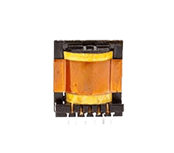
Figure 1: Custom High Frequency Flyback Transformers, Planar Cores, and Resonant Inductors engineered for OEM Power Converters.
A. Planar High-Frequency Transformers & Inductors
Planar magnetic structures replace traditional wire windings with stacked, multilayer printed circuit boards (PCBs) or flat copper stampings surrounded by low-profile planar ferrite cores (such as EQ, ER, or EFD shapes). Planar High-Frequency Magnetics deliver unmatched power density, predictable parasitic parameters, low thermal resistance, and exceptional repeatability across automated assembly processes.
- Ideal Topologies: Resonant LLC, Phase-Shifted Full-Bridge (PSFB), and Active Clamp Flyback converters.
- Key Benefit: Ultra-low profile height ($<10 \text{ mm}$) combined with high heat dissipation efficiency through mechanical chassis contact.
B. Custom Litz-Wound Switch-Mode Transformers
For high-frequency applications carrying heavy AC currents (ranging from tens to hundreds of amperes), solid copper wire suffers from extreme skin effect depth restrictions. Triad designs custom transformers utilizing engineered Litz wire—consisting of hundreds to thousands of individually insulated copper strands twisted in specific geometric patterns—to equalize current density and minimize high-frequency AC copper losses.
- Operating Frequency Range: 80 kHz to 1.5 MHz.
- Custom Interleaving: Primary-Secondary interleaving designs engineered to reduce leakage inductance down to sub-microhenry levels.
C. Resonant & Energy Storage High-Frequency Inductors
High-frequency energy storage inductors require precise air-gap engineering to prevent magnetic core saturation under high peak currents. Triad manufactures custom high-frequency inductors using distributed air-gap powder cores or precision-gapped ferrite cores to optimize energy storage density while suppressing fringing flux losses.
D. Wide-Bandgap Gate Drive & Isolation Transformers
As SiC MOSFETs and GaN HEMTs switch at ultra-fast $dV/dt$ rates exceeding $100 \text{ V/ns}$, drive circuitry requires low-capacitance isolation transformers to prevent common-mode noise coupling and ground loops. Triad’s specialized gate drive transformers provide reinforced insulation, high isolation voltages (up to $4000 \text{ VAC}$), and inter-winding capacitance under $10 \text{ pF}$.
Need Custom Engineering Specifications for Your Power Architecture?
Download our technical catalog or speak directly with a senior magnetics design engineer to evaluate your custom high-frequency requirements.
Get Catalog3. Technological Evolution & Future Development Trends (2025–2030)
The field of custom magnetics is undergoing significant transformation driven by material science, thermal engineering, and automated production technologies. Global procurement teams must align with suppliers capable of navigating these rapid shifts.
1. Wide-Bandgap (GaN/SiC) Semiconductor Synergy
The commercial adoption of Gallium Nitride (GaN) and Silicon Carbide (SiC) semiconductors has shifted power electronics switching speeds into megahertz frequencies. However, operating at $1 \text{ MHz+}$ shifts the primary system bottleneck from the semiconductor switches to the passive magnetics. Core loss equations ($P_v = k \cdot f^a \cdot B^b$, Steinmetz equation) indicate exponential loss increases with frequency. Future high-frequency custom magnetics rely heavily on ultra-low-loss MnZn ferrite formulations and advanced core shaping to control hysteresis and eddy currents.
2. Advanced Core Materials: Nanocrystalline & Thin-Film Ferrites
Traditional ferrite core materials encounter saturation flux density ($B_s$) roll-offs at elevated operating temperatures ($100^\circ\text{C} - 125^\circ\text{C}$). Next-generation custom high-frequency magnetics integrate nanocrystalline ribbon cores and ultra-thin high-permeability magnetic alloys. These materials offer saturation flux densities above $1.2 \text{ T}$ (compared to $0.4 \text{ T}$ for standard ferrites), enabling significant size reduction in high-power choke and inductor applications.
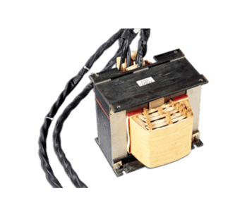
Figure 2: Precision winding, potting, and core shielding techniques engineered at Triad Magnetics for high-reliability OEM platforms.
3. Automated Planar PCB Integration & Additive Manufacturing
Manual bobbin winding introduces variability in leakage inductance and parasitic capacitance. The future of high-frequency custom magnetics lies in fully automated planar magnetic assembly. By embedding magnetic cores directly into substrate PCBs or utilizing automated multi-axis Litz winding, component-to-component electrical tolerance is tightened to under $\pm 2\%$, eliminating tuning steps in customer production lines.
4. Thermal Management Innovations & Direct-Heat-Sink Potting
High power density inherently concentrated thermal energy into smaller physical volumes. Modern high-frequency custom magnetics incorporate thermally conductive potting compounds (up to $3.0 \text{ W/m}\cdot\text{K}$ thermal conductivity), aluminum shell enclosures, and integrated heat-pipes. This thermal coupling allows heat generated in the core and windings to conduct directly to external cold plates or system chassis.
4. Global OEM Procurement Trends & Supply Chain Resilience
Global procurement executives faced with economic volatility, supply chain disruptions, and stringent regulatory demands are changing how they source custom magnetic components. Strategic sourcing now prioritizes total supply chain resilience over short-term component unit pricing.
A. Dual-Shoring Strategy: Local Prototyping + Global Mass Production
To reduce time-to-market risks, leading OEMs choose magnetics manufacturers offering a seamless dual-shore operational model. Rapid engineering iterations, initial samples, and pilot production runs occur locally within domestic engineering centers (such as Triad's Perris, California facility). Once the design is frozen, high-volume production transitions smoothly to cost-optimized offshore facilities (such as Triad's ISO-certified operations in the Philippines), securing cost targets without compromising engineering standards.
B. Total Cost of Ownership (TCO) vs. Initial Unit Price
Procuring low-cost magnetics from unverified suppliers frequently results in hidden costs: high field-failure rates, non-compliance with EMI standards, batch-to-batch inductance drift, and production line downtime. TCO analysis highlights the value of partnering with established manufacturers who guarantee 100% automated electrical testing, strict MIL-STD / IPC quality control, and full material lot traceability.
C. Stringent Regulatory & Environmental Compliance
Global market access requires strict compliance with international standards. Custom magnetics suppliers must provide comprehensive documentation for:
- Safety Standards: UL 62368-1 (Audio/Video & IT Equipment), IEC 60601-1 4th Edition (Medical Electrical Equipment), UL 1446 (Insulation Systems Class B through Class H).
- Environmental Regulations: RoHS3 (EU 2015/863), REACH SVHC compliance, Conflict Minerals reporting, and California Prop 65 certification.
5. The Triad Magnetics Advantage: 75+ Years of Engineering Excellence
When selecting a manufacturing partner for Custom High Frequency Magnetics, engineering heritage, quality infrastructure, and operational reliability are essential considerations. Triad Magnetics provides over seven decades of technical leadership in magnetic component design.
Figure 3: Triad Magnetics state-of-the-art engineering center and manufacturing hub supporting global OEM buyers.
Core Manufacturing Strengths at a Glance
- 75+ Years of Industry Leadership: Established in 1946, pioneering transformer innovation from early audio circuits to modern space-grade and wide-bandgap power systems.
- ISO 9001:2015 Certified Quality Management: Rigorous quality assurance processes, advanced 3D CAD simulation, 100% automated electrical testing, and full raw material traceability.
- Extensive Standard Baseline Catalog: Over 5,000 standard catalog part numbers available for immediate prototyping, providing a baseline to accelerate custom design iterations.
- Dual-Shore Manufacturing Flexibility: U.S. engineering, rapid prototyping, and quick-turn production in Perris, California, backed by high-capacity, low-cost mass production facilities in the Philippines.
- In-House Safety Testing & Agency Compliance: Engineering team experienced in navigating UL, CSA, VDE, TUV, and CE certification pathways, ensuring first-pass approval for your custom assembly.
6. Comprehensive Engineering & Procurement FAQ
Below are authoritative responses to the most critical technical and procurement questions asked by engineering teams and buyers evaluating custom high-frequency magnetic components.
Minimizing parasitic capacitance ($C_p$) and leakage inductance ($L_k$) requires precise winding topologies and core selection. Interleaving primary and secondary windings (e.g., P-S-P or P-S-S-P sandwich structures) increases magnetic coupling, reducing leakage inductance by up to 80%. However, excessive interleaving increases inter-winding capacitance. To strike the optimal balance, Triad engineers employ specialized high-dielectric margin tape, controlled layer spacing, low-profile planar core geometries (such as EQ or EFD shapes), and custom Litz wire turns ratios optimized through finite element analysis (FEA).
For operating frequencies between 500 kHz and 1.5 MHz, advanced Manganese-Zinc (MnZn) power ferrites featuring high flux density saturation ($B_s \approx 400-500 \text{ mT}$) and ultra-low core loss density (such as 3F4, 3F45, N97, or N49 materials) are standard. When frequencies surpass 1.5 MHz to 3 MHz+, Nickel-Zinc (NiZn) ferrites or specialized nanocrystalline formulations become necessary to suppress high hysteresis and eddy-current power dissipation. Triad’s design team matches core flux density ($B_{\text{max}}$) limits to your operating thermal profile ($85^\circ\text{C}$ to $125^\circ\text{C}$).
At frequencies above 50 kHz, AC current shifts toward the outer skin of a solid conductor (skin effect), reducing the effective cross-sectional area of the copper. Concurrently, magnetic fields from adjacent turns force current into localized channels (proximity effect), sharply driving up high-frequency AC resistance ($R_{ac}$). Litz wire consists of multiple individually insulated copper strands twisted in precise geometric patterns. This forces equal current distribution among all strands, drastically reducing skin and proximity losses and preserving copper thermal limits in high-power converters.
For industrial automation and power supplies, high-frequency custom magnetics must comply with UL 62368-1 (which replaced UL 60950-1) and IEC/EN 61558. For medical device power supplies, components must conform to IEC 60601-1 3rd/4th Edition, requiring double or reinforced insulation barriers, 2x MOPP (Means of Patient Protection), high dielectric isolation test voltages (up to $4000 \text{ VAC}_{\text{RMS}}$), and strict creepage and clearance distances (typically $\ge 8.0 \text{ mm}$). Triad designs UL Class B ($130^\circ\text{C}$), Class F ($155^\circ\text{C}$), and Class H ($180^\circ\text{C}$) insulation systems tailored to these requirements.
Triad operates an ISO 9001:2015 certified dual-shore model. Engineering design, magnetic modeling, fast-turn prototyping, and short-run production take place at our headquarters in Perris, California. High-volume mass production takes place at our wholly-owned, ISO-certified manufacturing plant in the Philippines. This guarantees engineering continuity, domestic customer service, supply chain redundancy, 100% automated electrical screening, and complete lot traceability for global procurement teams.
Standard prototyping timeline for custom high-frequency transformers and inductors ranges from 2 to 4 weeks depending on core tooling availability and custom bobbin/PCB layout requirements. Expedited engineering turnarounds are available when leveraging Triad’s extensive baseline inventory of standard core frames and bobbin tooling.
Ready to Partner with a Senior Magnetics Engineer?
Accelerate your project timeline with custom magnetics engineered specifically for your topology. Access our complete technical catalog or consult directly with our US-based engineering team.
Get Catalog