Discover expert articles, design guides, and technical solutions for magnetic components, power electronics, and custom transformer applications.
The 2026 market for Custom High Frequency Magnetics is becoming more demanding, not merely larger. Smaller converters, faster switching devices, and tighter thermal limits are reshaping supplier selection. A transformer that looks excellent on paper may still overheat beside a silicon carbide module.
MarketsandMarkets’ 2024 Power Electronics Market report identifies rising demand for high-efficiency conversion across electric vehicles, renewable energy, data centers, and industrial automation. Yole Group’s recent power electronics analysis also highlights wide-bandgap semiconductors as a major driver of higher switching frequencies and greater power density. These trends create opportunities for specialized magnetic-component manufacturers. They also expose weak designs quickly.
Dr. Charles R. Sullivan, a recognized researcher in power magnetics, has stated, “High-frequency magnetics design is fundamentally a trade-off between loss, size, and manufacturability.” That principle remains practical. A 100-kilohertz prototype can behave differently after production tolerances, insulation changes, or twenty minutes of thermal cycling. Experience matters here.
This guide evaluates the 2026 Best Custom High Frequency Magnetics Manufacturers through engineering capability, material selection, winding precision, testing, documentation, and delivery reliability. It considers ferrite geometry, leakage inductance, copper losses, creepage distance, and thermal performance. Certifications matter, but they do not replace measured data.
The category itself is imperfectly reported. Public market studies rarely isolate custom high-frequency magnetics, so comparisons require careful interpretation. That limitation deserves attention. A credible manufacturer should provide test curves, sample evidence, failure analysis, and realistic efficiency figures—not attractive claims alone.
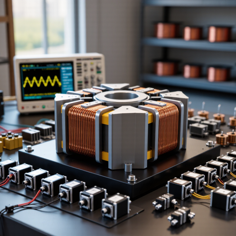
Custom high frequency magnetics are magnetic components engineered for a specific electrical and mechanical duty. They include transformers, inductors, chokes, and current sensors. Unlike standard parts, their core material, winding geometry, insulation, and thermal path match the converter design. Operating frequencies commonly range from tens of kilohertz into the megahertz range. Small changes matter.
An IEA Renewables 2024 report states that global renewable capacity additions reached about 510 GW in 2023. This expansion increases demand for compact, efficient power converters. Custom magnetics help reduce switching losses, electromagnetic interference, and unnecessary enclosure space. Engineers select ferrite cores, litz wire, copper foil, or planar windings according to frequency and current density. A 2024 power electronics market analysis also projects sustained growth through 2030, strengthening the need for application-specific components.
Performance depends on more than inductance values. Designers must verify leakage inductance, creepage distance, insulation systems, temperature rise, and acoustic noise. Testing should include load cycling, dielectric withstand, partial-discharge checks, and thermal imaging. IEC 61558 and IEC 60664 provide useful safety references. Still, no design is perfect. A transformer that passes bench testing may overheat inside a sealed enclosure. Early prototypes can also expose unexpected parasitic capacitance. Careful measurement, documented tolerances, and cooperation between the magnetics engineer and converter designer remain essential.
| Category | Parameter | Typical or Applicable Information | Engineering Note |
|---|---|---|---|
| Definition | Custom high frequency magnetics | Engineered magnetic components designed for a specified electrical frequency, power level, insulation system, thermal limit, mechanical envelope, and application requirement. | Common custom products include transformers, power inductors, coupled inductors, common-mode chokes, current transformers, and signal transformers. |
| Operating Range | Typical switching frequency | Many power applications operate from approximately 20 kHz to 1 MHz. RF and signal magnetics can operate from hundreds of kilohertz to several hundred megahertz, depending on construction and material. | The usable frequency is determined by core loss, winding capacitance, leakage inductance, skin effect, proximity effect, and required waveform quality. |
| Core Material | Manganese-zinc ferrite | Widely used for power transformers and inductors from low switching frequencies through the lower hundreds of kilohertz, with high permeability and relatively low core loss in the appropriate range. | Material selection should be based on manufacturer loss curves at the actual flux density, temperature, and frequency. |
| Core Material | Nickel-zinc ferrite | Commonly used for higher-frequency signal transformers, broadband transformers, EMI suppression components, and inductive parts requiring high electrical resistivity. | It generally offers lower parasitic capacitance and higher resistivity than many lower-frequency ferrite materials, but its power capability depends strongly on geometry. |
| Core Material | Nanocrystalline alloy | Used where high permeability, high saturation flux density, compact size, and strong common-mode noise attenuation are required, often across tens of kilohertz to the low megahertz range. | The material can reduce size or winding turns, but cost, mechanical handling, insulation, and high-frequency loss must be evaluated together. |
| Core Material | Powdered iron or distributed-gap material | Used primarily for energy-storage inductors because the distributed air gap provides useful DC-bias capability and controlled inductance behavior. | Core loss and temperature rise can become significant at high frequency; the selected grade must be matched to ripple current and operating frequency. |
| Component Type | High-frequency transformer | Provides galvanic isolation, voltage conversion, impedance matching, or multiple regulated secondary outputs in switched-mode power supplies and isolated converters. | Key design inputs include input voltage, output voltage, power, switching frequency, turns ratio, isolation voltage, creepage, clearance, and duty cycle. |
| Component Type | Power inductor | Stores energy and smooths current in buck, boost, buck-boost, resonant, and other switching converter topologies. | The required inductance must be specified together with peak current, RMS current, allowable ripple, DC resistance, saturation current, and temperature rise. |
| Component Type | Common-mode choke | Suppresses common-mode conducted electromagnetic interference while allowing the desired differential current to pass through the circuit. | Performance depends on common-mode impedance, differential-mode leakage inductance, current rating, winding balance, and parasitic capacitance. |
| Component Type | Current transformer | Produces a proportional isolated signal for current measurement, protection, control, or feedback circuits. | Burden resistance, turns ratio, accuracy, phase error, excitation current, insulation, and maximum measurable current are essential specifications. |
| Electrical Design | Inductance tolerance | Typical production requirements may range from approximately ±5% to ±20%, depending on the component type, core material, air gap, and application. | Tighter tolerance may require controlled gapping, additional screening, precision winding, or post-assembly testing. |
| Electrical Design | DC resistance | Winding resistance is specified to control conduction loss, efficiency, voltage drop, and thermal performance. Values vary widely with current, copper size, winding length, and package size. | Resistance should be stated at a defined reference temperature because copper resistance increases with temperature. |
| Electrical Design | Saturation current | The current at which inductance falls by a defined percentage, commonly 10%, 20%, or 30% from its initial value. | The definition must be agreed in advance because different saturation-current criteria can produce substantially different rated values. |
| Electrical Design | Core loss | Power dissipated in the magnetic core due to hysteresis, eddy-current, and excess-loss mechanisms under the applied AC flux. | Core loss increases with frequency and flux density; manufacturer curves or validated test data should be used rather than relying only on nominal material labels. |
| Winding Technology | Wire selection | Designs may use round copper wire, rectangular wire, parallel strands, or litz wire according to current density, frequency, voltage, and available winding space. | At high frequency, skin effect and proximity effect can raise AC resistance well above the DC resistance. |
| Winding Technology | Winding configuration | Possible configurations include sectional windings, interleaved windings, bifilar windings, multilayer windings, foil windings, and separate primary-secondary chambers. | Interleaving can reduce leakage inductance but may increase interwinding capacitance; the correct balance depends on the converter topology and EMI targets. |
| Safety | Insulation system | Custom assemblies may require functional, basic, supplementary, reinforced, or double insulation, depending on the input voltage, working voltage, pollution degree, and end equipment. | Insulation tape, wire coating, bobbin design, margins, barriers, potting, and encapsulation must be selected as one coordinated system. |
| Safety | Creepage and clearance | Physical spacing requirements are determined by working voltage, transient voltage, insulation level, pollution degree, material group, and applicable safety requirements. | The final distances should be verified against the applicable product safety standard and the actual manufacturing tolerances. |
| Thermal Performance | Temperature rise | Permitted temperature rise is application-dependent and must account for ambient temperature, insulation temperature class, core loss, copper loss, airflow, and enclosure conditions. | A design that passes at room temperature may fail in a sealed enclosure or at elevated ambient temperature; thermal testing should use the intended operating conditions. |
| Mechanical Design | Package and form factor | Custom magnetics can be designed for through-hole, surface-mount, vertical, horizontal, low-profile, open-frame, encapsulated, or molded construction. | The mechanical drawing should define maximum dimensions, terminal layout, pin spacing, mounting method, keep-out areas, and component orientation. |
| EMI Performance | Parasitic parameters | Leakage inductance, interwinding capacitance, self-resonant frequency, stray magnetic field, and winding-to-core capacitance influence high-frequency behavior. | These parameters should be measured or modeled because they can affect switching spikes, ringing, common-mode current, and control-loop stability. |
| Manufacturing | Customization capabilities | A qualified manufacturer should be able to support magnetic design, core selection, winding development, insulation construction, thermal evaluation, prototypes, process documentation, and production testing. | The best supplier is not defined only by unit price; repeatability, engineering support, traceability, testing, and delivery capability are equally important. |
| Quality Control | Typical production tests | Common tests include inductance, turns ratio, DC resistance, polarity, hi-pot or dielectric withstand, insulation resistance, no-load current, loss, and visual inspection. | Test limits, test frequency, test voltage, fixture configuration, sampling plan, and calibration requirements should be documented before mass production. |
| Applications | Typical end uses | Applications include telecommunications power, data-center power supplies, renewable-energy converters, electric-vehicle charging systems, industrial automation, lighting drivers, medical equipment, consumer electronics, and automotive electronics. | Each application imposes different requirements for isolation, efficiency, vibration, temperature, electromagnetic compatibility, reliability, and certification. |
| Supplier Evaluation | Recommended qualification criteria | Evaluate technical design capability, material traceability, prototype speed, process control, automated winding or inspection, test coverage, failure analysis, documentation, capacity, and supply-chain resilience. | A complete request for quotation should include electrical specifications, mechanical drawings, safety requirements, environmental conditions, annual volume, and acceptance criteria. |
| Specification Inputs | Minimum information for a custom design | Provide topology, input and output ranges, rated and peak power, operating frequency, waveform, duty cycle, isolation voltage, current profile, ambient temperature, dimensions, mounting method, and applicable compliance requirements. | Incomplete specifications often lead to oversized components, excessive temperature rise, unexpected EMI, or repeated redesign during qualification. |
Note: The values and ranges shown are representative engineering guidance. Final ratings must be validated through material data, prototype testing, thermal testing, safety review, and the requirements of the finished equipment.
They are transformers, inductors, chokes, or current sensors designed for one electrical application. Their core, windings, insulation, and cooling path match the converter. Small changes matter.
Custom parts can reduce switching losses, electromagnetic interference, and enclosure space. They also fit unusual current, voltage, and frequency requirements. Standard parts may waste space.
Engineers may select ferrite cores, litz wire, copper foil, or planar windings. The choice depends on frequency, current density, heat, and available space. There is no universal winner.
Check inductance, leakage inductance, saturation behavior, insulation, creepage, and temperature rise. Also review acoustic noise and parasitic capacitance. Inductance alone is insufficient.
Test samples at low input voltage, high load, and elevated ambient temperature. Include load cycling, dielectric withstand, thermal imaging, and insulation checks. Measure real conditions.
A part may perform well at 25°C but overheat near 70°C inside a sealed cabinet. Nearby switching devices can add heat and electrical noise. Bench results are incomplete.
Request measured curves, thermal images, insulation data, and production-intent samples. Ask how the core, winding structure, copper thickness, and cooling path were selected. Vague answers deserve caution.
Review winding tension, insulation placement, solder quality, magnetic gaps, and dimensional tolerances. Ask how materials and batches remain traceable. Small defects can grow.
The supplier and converter designer should review frequency, current, temperature, insulation, and board space. Small pilot runs can reveal unexpected heating or capacitance. Redesigns are expensive.
Custom High Frequency Magnetics are specialized magnetic components designed to operate efficiently at elevated switching frequencies, supporting compact, high-performance power and signal systems. This article explains their core structure, operating principles, and the key technologies behind them, including advanced magnetic materials, optimized winding methods, thermal management, shielding, and precision manufacturing. It also outlines how custom designs can improve efficiency, reduce electromagnetic interference, and meet demanding electrical and mechanical requirements.
The guide presents practical criteria for evaluating manufacturers, such as engineering expertise, material quality, design flexibility, testing capabilities, production consistency, and compliance with relevant industry standards. It also reviews major application areas, including power supplies, telecommunications equipment, electric vehicles, renewable energy systems, industrial controls, and high-speed electronic devices. By comparing technical needs, operating conditions, reliability expectations, and total cost, readers can make more informed decisions when selecting a Custom High Frequency Magnetics partner for specialized projects.